
It is an unfortunate fact that many fine shapers are still available but their vises are missing. Unfortunately I currently find myself in the same boat. You can find them on eBay but usually they cost almost as much as you may have paid for your shaper. There are also some nice new vices available which will work just fine. But the third alternative is to build your own.
Bill Cleary in Pensacola Florida just did exactly this. Here is his story:
“When I purchased my 7 inch South Bend shaper at a local school auction in 2005, it was complete and working, with the exception of a vise.
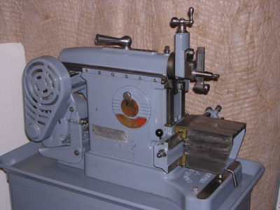
Restored South Bend
Photo by Bill Cleary
The vises on eBay were very expensive and the little drill press vise I had kept slipping. When I saw these drawings for an AMMCO Shaper vise on the internet, I decided to make my own vise:
http://lathe.com/YahooGroups/Files/Metal_Shapers/ShaperVise.pdf
If you join the Yahoo group – “Lewis_Machine_Tool” which is dedicated to the Lewis family of machines, you will have access to the file “shaper_vise.exe” which is a self-executing file that contains 3-D drawings.
Many thanks to Keith Violette for the excellent drawings and Art Volz for preserving them!
I made the vise from Fortal, an aluminum alloy which is supposed to have the strength of steel. See the excellent article "A Unique Mill Vise - Junior Edition," by Donald L. Feinberg on page 26 of the December 2004/January 2005 issue of Machinist's Workshop. He provides a good bit of information on Fortal. I bought my Fortal from www.mousebar.com, who have apparently closed shop, so if anyone out there knows a good source, please let us all know. Fortal is a very friendly material for the home shop, since it can be cut with wood working tools like a carbide table saw blade. I also used a metal cutting band saw blade, but Mr. Feinberg states that a woodworking band saw could be used.
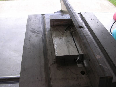
Table Sawing Fortal
Photo by Bill Cleary
Incidentally, my band saw was homemade over 20 years ago from a "metal parts kit" made by Gilliom Mfg. of St. Charles, Missouri, and is still the most frequently used tool in my shop!
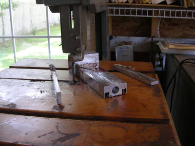
Band Sawing Fortal
Photo by Bill Cleary
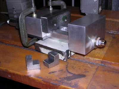
My vise was patterned after the drawings in the two references, but was scaled to a slightly narrower width because of the width of the size of Fortal on hand. I incorporated a couple of novel improvements which you may notice in the photographs. The first idea is to use “hardware store fasteners” for simplicity and low cost.
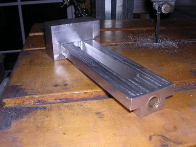
Vise Roughed Out
Photo by Bill Cleary
I used ¾” scrap steel for the moving jaw, lock blocks and swivel base. A piece of ½” steel was used for the fixed jaw.
The first key piece is the moving jaw. I shaped it into a T shape so that the thick top part of the T is the actual moving jaw which contacts the work being held. The ¼” thick steel gibs are fastened to the bottom of the Fortal guide block.
Side View with Lock Blocks
Photo by Bill Cleary
The lower part of the T shaped moving jaw is drilled and tapped for the leadscrew. I used a piece of RH thread, ½-13 rod which I will probably replace with a piece of LH thread rod sometime. This lower part was very carefully hand fit to the central opening so there is very little play. The top of the T of the moving jaw extends ½” beyond each side of the body or base of the vise. The thick steel of the moving jaw hanging out over the sides creates the ideal space for an L shaped block.
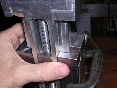
Bottom View of Lock Blocks
Photo by Bill Cleary
The block becomes a lock when it is drilled and tapped down from the top (I used a #10 Socket head cap screw countersunk). The lock block dimensions are 1” square, ¾” thick with a ½” x ½” notch cut on the inside portion, so that it nestles perfectly under the top of the T of the moving jaw, outboard the base or body of the vise, and under the vise body slide as shown in the picture above. It stays in position due to the fact that it is in contact with the steel plate gibs and it has the #10 SHCS holding it from above. The only thing the photo does not show is the drilling, tapping and countersinking operation.
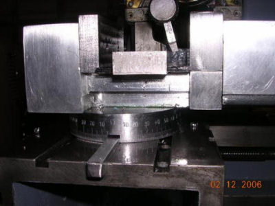
Swivel Base with Marks
Photo by Bill Cleary
The lock blocks work quite effectively, and they are a practical solution to the eternal problem of the moving jaw rocking backward when clamping the work.
The swivel base is marked every 10 degrees with 3/32” number stamps. It is patterned after a Geo. Thomas designed rotary table I built from drawings and instructions sold by Mr. Guy Lautard at:
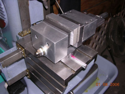
Vise in Use
Photo by Bill Cleary
I am very pleased with the look and usefulness of the vise.
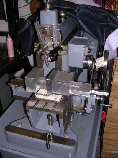
Shaper Complete with Vise
Photo by Bill Cleary
I hope this brief outline will be helpful to readers of the Shaper Column.”
Thanks Bill for sharing this information.
Keep sending me email with questions and interesting shaper stories.
My email address is KayPatFisher@gmail.com.