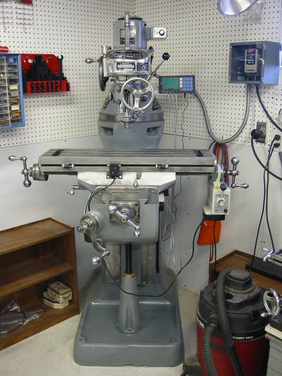
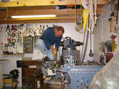
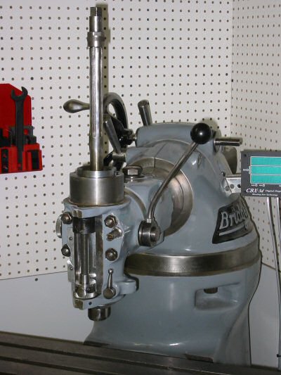
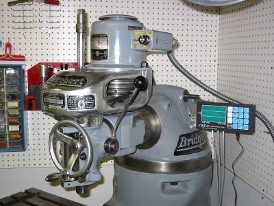
| Bridgeport Round Ram M-Head - After | Photo by Kay Fisher |
At the September 2001 NEMES meeting, Ken Malsky offered an old M-head Bridgeport mill for sale for $300. I figured that it would go fast. At the October 2001 meeting I asked Ken if he sold the mill. To my shock he had not. I told him that I would take it on two conditions. One - it had to fit in my basement. Two - I would need some time to move it since I had done no planning. We shook hands on the deal.
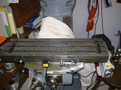
After some email exchanges it was determined that it would indeed fit in my basement exactly where my current mill (a Clausing 8520) was sitting. The old round ram M-head Bridgeports are the shortest mills that Bridgeport ever made. This one had a 32-inch table (the smallest Bridgeport ever produced) and a 9-inch knee instead of the now more common 12-inch knee.
The Bridgeport came with a home-brew 1->3 phase rotary converter. This was an idler style arrangement with a large heavy motor. Ken also offered free a replacement C-face single-phase motor and an aluminum plate suitable for mounting it and a few Morse #2 collets (1/2", 3/8", 1/4").
I passed on the motor accessories. I knew that I would want to power the mill with a VFD so that saved me hauling away the two extra heavy motors.
We lightened the mill by removing the head, the motor, and the table. The head and motor came off easily. The table caused us some head scratching. First we removed the original Bridgeport longitudinal power feed assembly, which I did not intend to use. Then we thought we would just slide the table off the end. What we didn’t account for was the extreme wear. As the table moved off center, it tightened up considerably. After we discovered how to loosen the adjustable gib, it came off easily. I managed to put the motor, head, longitudinal power feed, and table in the trunk of my Mustang.
I arranged for help from a friend with a flatbed trailer that he uses for moving cars. Ken Malsky’s neighbor had a brand new backhoe. We rolled the mill out of Ken’s garage on the homemade pallet with four casters. His neighbor wrapped a chain around the ram, picked it up with his backhoe, and sat it on my neighbor’s trailer. We were a little anxious while the backhoe laid the mill on it’s back, but it went over without any fuss.
After we drove the trailer and chained down mill to Orange, I called a local tow truck. For $35, he picked up the mill with a sling around the ram and slid it down the basement bulkhead stairs on two 2x10 planks.
At this point I had the mill in my basement and proceeded to take it “completely” apart. After many hours of work on the mill I was given the chance to take an early retirement package when Hewlett Packard bought out Compaq. So we sold the house and moved to Mesa Arizona. Again, I hired the local tow truck operator. He picked up the base column, turret, and ram as one assembly and sat it in my driveway. I rolled it into the garage on its homemade pallet. The fellow who bought my house had access to a large truck with a lift gate. On moving day, we put it on his lift gate and raised it to the moving van and rolled it in. After we got settled in Arizona and the movers arrived, we used a bobcat with a forklift front end to pick it out of the van and place it in my new workshop.
To maneuver it around the basement and shop I raised the edge of the base unit with a crowbar and placed steel rods under it so I could roll it around.
The base unit weighs around 900 pounds and the complete milling machine around 1900 pounds. The base unit and the knee were the only two pieces that I could not pick up alone.
Bridgeport manuals are readily available on the Internet, on eBay, and from friends at NEMES. My current favorite manual is part of a CD that I got from Errol Groff for $10.
Errol sells a CD that started out devoted to shapers but has expanded to many other types of machines. Included on it is the M-105H Bridgeport Series I Milling Machine Installation, Operation and Maintenance Manual. A total of about 450 Meg of information for $10.00 shipping included. If you would like to just download the 2.4Mb Bridgeport manual click here.
Errol accepts cash, check, money order and PayPal. He has shipped out about 150 copies and has yet to have anyone ask for a refund.
Latest CD Contents as of 14 Jan 2003
Bridgeport Manuals
         1981 Programming Manual
         1983 Programming Manual
         R2E3 Manual
         Series II NC Programming Manual
         Student Manual
         Bridgeport Series 1 Install, Operate and Maintain
                  Manual
         Quick Change Tooling for the J Head
Brown and Sharpe
         No. 3 Mill Manual
Fundamentals of Machine Tools
Grinding and Lapping
         1907 Treatise on Grinding and Lapping
Grinding Dressers
         J and S Fluidmotion
         Optidress Manual
         Selecting the Right Grinding Wheel (Norton)
         Tangential Wheel Dresser
Jacobs Chuck
         Jacobs Rubber Collet Chuck
Leblond 15 and 19 Inch Lathes
         Leblond Manual
Machinery Repair
Odds and Ends
         Thread Elements Jones and Lamson
Shaper Work
Shapers - Chapter 1 and 2 Machine Tool Operation
Errol Groff
180 Middle Road
Preston, CT 06365 8206
Errol Groff
Instructor, Machine Tool Department
H.H. Ellis Technical School
(860) 774-8511
Home Page:
http://pages.cthome.net/errol.groff/
One source for Bridgeport information is the Yahoo group “Bridgeport_Mill” which
you can join at http://groups.yahoo.com/.
Another is Tony Griffiths’ machine tool information website. This site has information about many machines, including lathes and mills. The Bridgeport area includes descriptions of accessories that haven’t been made in years:
This chart is a cross reference from Bridgeport serial numbers to date of manufacture including an estimate of the number produced each year:
| Round Ram | ||
| Year | Serial Number Range | # Made |
| 1938 | BH-1 thru BH-39 | 39 |
| 1939 | BH-40 thru BH-252 | 213 |
| 1940 | BH-253 thru BH-656 | 404 |
| 1941 | BH-657 thru BH-1549 | 893 |
| 1942 | BH-1550 thru BH-2943 | 1394 |
| 1943 | BH-2944 thru BH-4105 | 1162 |
| 1944 | BH-4106 thru BH-4997 | 892 |
| 1945 | BH-4998 thru BH-5930 | 933 |
| 1946 | BH-5931 thru BH-7235 | 1305 |
| 1947 | BH-7236 thru BH-8814 | 1579 |
| 1948 | BH-8815 thru BH-10381 | 1567 |
| 1949 | BH-10382 thru BH-11378 | 997 |
| 1950 | BH-11379 thru BH-12750 | 1372 |
| 1951 | BH-12751 thru BH-14489 | 1739 |
| 1952 | BH-14490 thru BH-16700 | 2211 |
| 1953 | BH-16701 thru BH-19367 | 2667 |
| 1954 | BH-19368 thru BH-22732 | 3365 |
| 1955 | BH-22733 thru BH-26962 | 4230 |
| Start V Ram | ||
| 1956 | BR-26963 thru BR-31618 | 4656 |
| 1957 | BR-31619 thru BR-37278 | 5660 |
| 1958 | BR-37279 thru BR-42110 | 4832 |
| 1959 | BR-42111 thru BR-46938 | 4828 |
| 1960 | BR-46939 thru BR-52598 | 5660 |
| 1961 | BR-52599 thru BR-58552 | 5954 |
| 1962 | BR-58553 thru BR-64987 | 6435 |
| 1963 | BR-64988 thru BR-71981 | 6994 |
| 1964 | BR-71982 thru BR-79538 | 7557 |
| 1965 | BR-75939 thru BR-88180 | 8642 |
| 1966 | BR-88181 thru BR-98089 | 9909 |
| 1967 | BR-98090 thru BR-108351 | 10262 |
| 1968 | BR-108352 thru BR-118640 | 10289 |
| 1969 | BR-118641 thru BR-131778 | 13138 |
| 1970 | BR-131779 thru BR-138139 | 6361 |
| 1971 | BR-138640 thru BR-143350 | 5211 |
| 1972 | BR-143351 thru BR-149294 | 5944 |
| 1973 | BR-149295 thru BR-157909 | 8615 |
| 1974 | BR-157910 thru BR-167652 | 9743 |
| 1975 | BR-167653 thru BR-174083 | 6431 |
| 1976 | BR-174084 thru BR-180697 | 6614 |
| 1977 | BR-180698 thru BR-188559 | 7862 |
| 1978 | BR-188560 thru BR-196987 | 8428 |
| 1979 | BR-196988 thru BR-206296 | 9309 |
| 1980 | BR-206297 thru BR-216473 | 10177 |
| 1981 | BR-216474 thru BR-227523 | 11050 |
| 1982 | BR-227524 thru BR-231700 | 4177 |
| 1983 | BR-231701 thru BR-235985 | 4285 |
| 1984 | BR-235986 thru BR-241350 | 5365 |
| 1985 | BR-241351 thru BR-246659 | 5309 |
| 1986 | BR-246660 thru BR-248551 | 1892 |
| 1987 | BR-248552 thru BR-250531 | 1980 |
| 1988 | BR-250532 thru BR-252874 | 2343 |
| 1989 | BR-252875 thru BR-255463 | 2589 |
| 1990 | BR-255464 thru BR-257888 | 2425 |
| 1991 | BR-257889 thru BR-259897 | 2009 |
| 1992 | BR-257898 thru BR-262188 | 2291 |
| 1993 | BR-262189 thru BR-264586 | 2398 |
| 1994 | BR-264587 thru BR-267635 | 3049 |
| 1995 | BR-267636 thru |
The main serial number, shown in the above chart, is located on the top of the knee in the front. Mine is #7365, which did not include the “BH” prefix. To expose the serial number, crank the saddle back towards the column until the chip guard plate slides back an inch. My Bridgeport was manufactured in 1947 – the same year I was born.
The door contains the full serial number BH7365, which matches the knee. It also has a patent number 2275291, which matches one on the table. The Saddle has a serial number on the left side next to the table lock handle. It should match the table serial number. Mine is #527. I don’t remember where the table serial number is. I suspect it is under the left or right bearing bracket. It really doesn’t matter as it was used during assembly at the factory to insure the surfaces that were hand scraped match up on the same machine. The table also has a patent number on the front center. Mine is #2275291. If anybody knows for sure where the table serial number is please let me know and I’ll update this paragraph.
Each dial and handle is stamped with an A, B, C, or D. The left handle and dial are A. There is also an A on the front left of the table. The right handle and dial are B. There is a B on the front right to match. The cross feed (Y axis) handle and dial are C. The elevating (Z axis) dial is D. They are machined to match and won’t fit as well anywhere else.
The M-Head serial number is on the left of the quill housing. Mine is #M21472. It should match the serial number on the belt housing.
The belt-housing serial number is on a label fastened to the front of the housing. Mine is #M21472. It should match the M-head serial number.
Not all motors have serial numbers. They changed type and manufacturers of motors over the years. Mine has a serial number on a label on the front of the motor. It is #3064.
Spare parts for Bridgeport mills are available from many places. My favorite for new parts is High Quality Tools.
They have an excellent catalog. You have to order from “High Quality Tools” through a distributor. I have ordered through:
In the past, experts at Rice Machinery answered my technical questions and have provided good service.
There are always parts for Bridgeport mills for sale on eBay:
Select the category “Business & Industrial” then select the sub category “metalworking”. Then search for “Bridgeport”.
The column was the largest single piece of the mill. I kept it on a homemade pallet skid and did all my refurbishing right where it landed from the move – at the door to the basement bulkhead. I put the knee on the column with a chain hoist because I could not pick it up by myself. Before I did this, I spent many hours hand scraping the dovetail precision surfaces and the adjustable gib.
| Column Cleaned and Chipped - Side | Photo by Kay Fisher |
| Column Cleaned and Chipped - Rear | Photo by Kay Fisher |
| Column After Painting - Side | Photo by Kay Fisher |
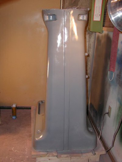
| Column After Painting - Rear | Photo by Kay Fisher |
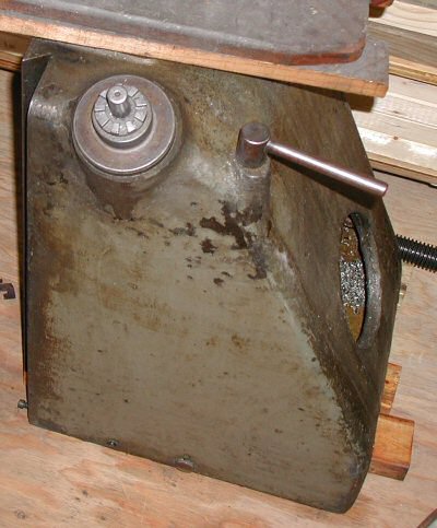
| Knee Before | Photo by Kay Fisher |

| Knee After Painting - Left Bottom | Photo by Kay Fisher |
| Knee After Painting - Right Bottom | Photo by Kay Fisher |
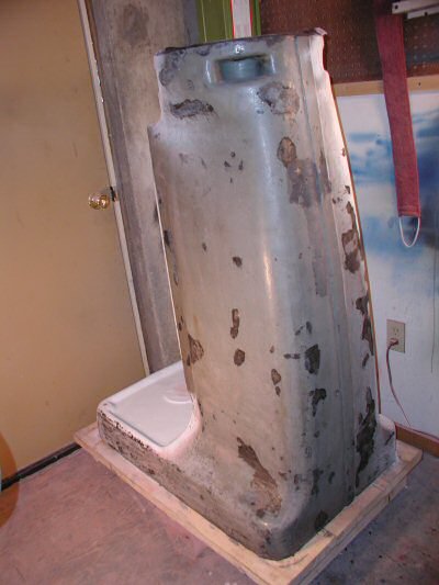
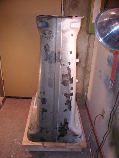
| Pedestal Before | Photo by Kay Fisher |
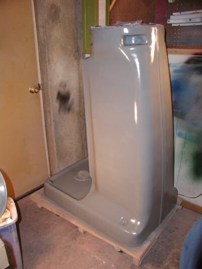
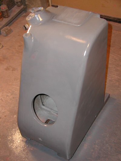
| Pedestal After | Photo by Kay Fisher |
| Knee Being Installed | Photo by Kay Fisher |
| Knee Installed | Photo by Kay Fisher |
The inside of the knee was by far the most messy part and not at all fun to clean up. I would wipe out goop and swarf and spray in some WD-40 and wipe some more then scrape gunk off. I thought it would never end.
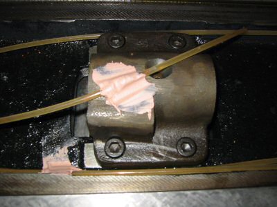
| Broken Bearing Cap and Replacement | Photo by Kay Fisher |
When I took the knee apart I discovered one broken part - the bearing cap. I priced one through High Quality Tools at $31.50 and decided to build my own.
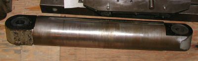
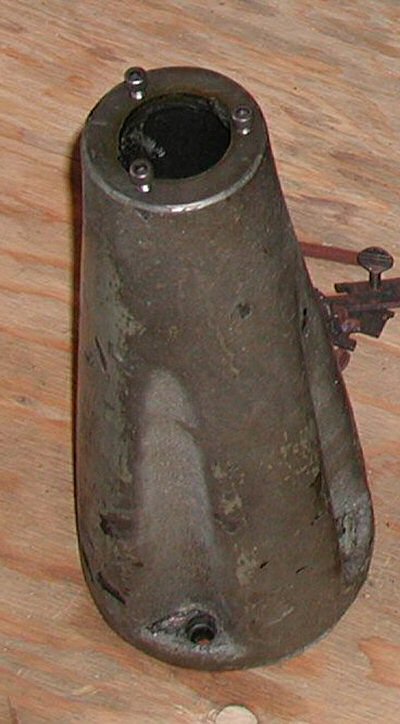
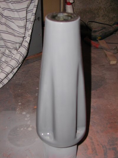
| Ram Before | Photo by Kay Fisher |
The only other part that I had to make was a table lock plunger, a little part about the size of a pencil eraser. Somehow, I managed to lose it during disassembly, moving, and reassembly.
The above photos show the refinishing of the column and knee. The procedure is simple enough: clean it up, chip off the bad paint, and apply new paint. The devil is in the details.
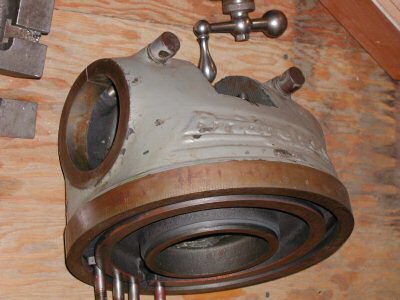
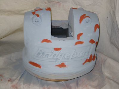
| Turret Before | Photo by Kay Fisher |
This is the way Bridgeport finished their cast iron parts in 1947. First they apply a layer of black shinny stuff that is very thick and acts much like our present day Bondo although with a considerable better finish. I cannot say that Bondo will last 57 years or more in a shop but I can say that the skim coat that Bridgeport applied was starting to lift in areas that had seen some stress and in protected areas.
I removed the old paint and their skim coat mostly by hand. I would have liked to just blast it off with some easy method. I tried various sanders and wire brushes but in the end what worked best for me was chipping with an old worn out straight slot screwdriver. My second favorite tool was a very nice wood chisel. Do not cringe. I have a Tormek Supergrind and am perfectly capable of restoring the edge on the wood chisel to better than new condition.

| Turret Bearing Ring Before | Photo by Kay Fisher |
I did not take any photos of the Bondo steps. I liberally applied a layer of Bondo brand body filler over the entire column, knee, and pedestal. At that stage it was all pink. Next I sanded with power sanders and by hand for hours.

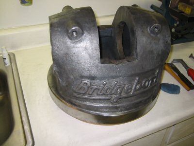
| Turret After Paint Scraping | Photo by Kay Fisher |
Then I filled all the imperfections with Bondo brand glazing and spot putty. Now it looked pink with dark red spots. Then I hand sanded again, filled with glazing putty again and repeated this cycle three or more times until perfect.
| Turret After Wire Brushing | Photo by Kay Fisher |
Then I sprayed Rust Oleum automotive primer (light gray) on the surface. Invariably this would expose more imperfections that I had not seen so I would again apply glazing putty and hand sand. Then I added another coat of primer, more glazing putty, and more sanding another three or more times.
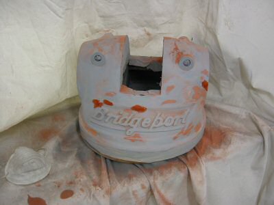
| Turret After Glazing Putty | Photo by Kay Fisher |
The last step was applying paint. The paint I chose to use was Rust Oleum gloss protective enamel (smoke gray) from Wal Mart. I can’t swear that it is extra hard or lasts a long time when exposed to grease but it was darn handy to buy and so far I have no complaints.
To bring out the shine of some of the cast iron surfaces – such as the graduations on the bottom of the turret, I used a combination of a wire brush and an abrasive flap wheel. I could get the best finish with the flap wheel but they wore out fast and good replacements were hard to find.
| Turret After Glazing Putty - Pass 2 | Photo by Kay Fisher |
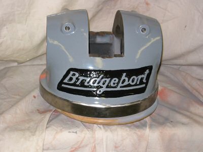
| Turret Finished | Photo by Kay Fisher |
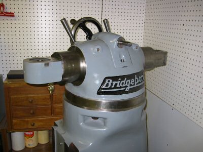
| Turret and Ram Installed | Photo by Kay Fisher |
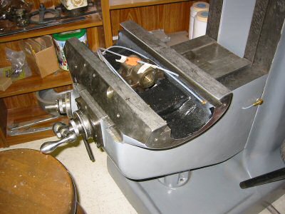
I cleaned and finished the saddle before I scraped it. After scraping it I decided to install a one-shot lube system. In the end I had to sand and paint again to repair nicks and scratches from handling.
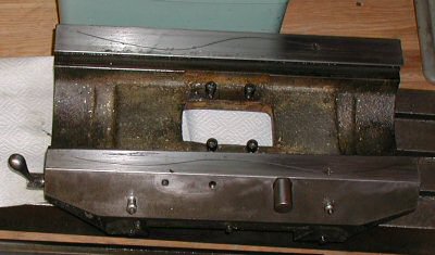
| Saddle Before | Photo by Kay Fisher |
| Saddle With Bondo | Photo by Kay Fisher |
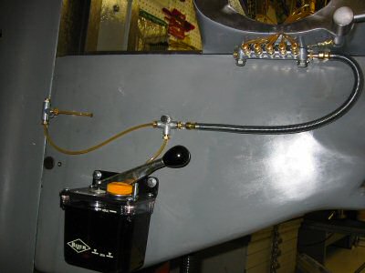
After spending many hours hand scraping 56 years of wear out of the base, knee, saddle, and table I would hate to wear them down prematurely. I always wanted a one shot lube system but after I purchased the manual lubricator and started looking into all the additional parts I would need - I started getting cold feet. When I moved from Massachusetts to Arizona and the one shot lube project went on hold for over a year. When I finished my work on the saddle I couldn’t bring myself to assemble it without a one shot lube system. Here is how I did it.
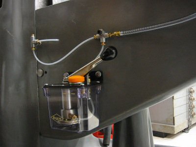
| Bijur Lubricator Installed | Photo by Kay Fisher |
They have an excellent catalog that has a small diagram of the lube system available from Lube USA. You have to order from “High Quality Tools” through a distributor. I have ordered through:
In the past, experts at Rice Machinery answered my technical questions. But even Rice Machinery wanted $233.75 for the Bijur manual lubricator. So I purchased my Bijur Manual Lubricator from ENCO for $76. It is model number 203 1500. They also have an ENCO brand for $39 - model number 203 1505.
After watching the web and trying local hardware stores I finally determined it was possible to save some money but it was not going to be a nickel and dime deal. One cost that stayed high was the meter units. Bijur wanted $9.88 to $17.63 for the meter units specified in their kit No. K 1099. Another vendor (Trico) is listed in the MSC catalogue but their meter units were approximately $10.00 each.
Lube USA had the most economical meter units fro $7.29 to $13.09, so I ordered all my plumbing and meters from them:
They were very professional yet didn’t seem to mind a small order from an individual. They also have an excellent catalog. If you ask, they will send you a one page “Bridgeport Milling Machine 9 Pt. Lubrication System” diagram that lists most of the part numbers you need to retrofit an existing Bridgeport mill.
Here is the part list of the items that I bought from Lube USA.
|
Qty |
Part # |
Item Description |
Price Each |
1 |
185052 |
HTG-0 Flow Adapter |
$13.09 |
1 |
185002 |
HAS-0 Flow Unit |
$7.29 |
1 |
186101 |
Elbow Connector |
$2.94 |
11 |
106271 |
Tubing Insert 4mm |
$0.41 |
13 |
106254 |
Compression Sleeve 4mm |
$0.31 |
7 |
186252 |
Compression Bushing |
$0.70 |
6 |
186251 |
Compression Nut |
$0.70 |
4 |
106901 |
Tube Ends Elbow, Drive 3mm |
$3.77 |
10ft |
106801 |
4mm Nylon Tubing, Natural |
$0.50 |
1 |
185009 |
HJB-0 Flow Unit |
$7.29 |
4 |
185010 |
HJB-1 Flow Unit |
$7.29 |
1 |
186404 |
PJ-7S Junction |
$13.09 |
1 |
106707 |
12" Flexible Hose 300mm |
$13.99 |
1 |
186420 |
PJ-3 Junction |
$4.14 |
2 |
186255 |
Closure Plug |
$0.69 |
UPS shipping |
$8.58 |
||
Total |
$138.67 |
The part numbers that start with 106 are metric. The part numbers that start with 185 and 186 are English. The output from the Bijur lubricator is 1/8” NPT as are the Bridgeport zerk oilers.
The list above is correct to the best of my knowledge. Originally I was a couple of items short and had to pay additional shipping cost for a couple of small parts. I advise anyone ordering to order extra compression sleeves, tubing, and drive barbs to allow for mistakes.
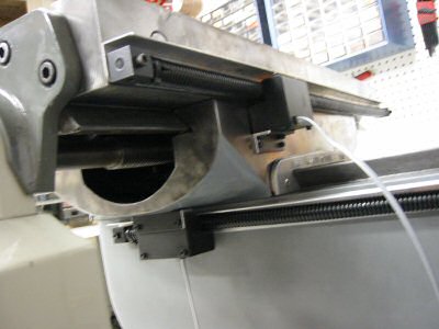
The new Bridgeports have 12 inches of Y travel where mine has 9 inches of travel. I measured a new Bridgeport mill and the lubricator was approximately 10.25” down from the top of the knee to the top of the lubricator and 4.5” from the back of the knee to the back of the lubricator.
Because my knee is smaller I placed my lubricator 7.25” down from the top of the knee and 4.25” from the back. I mounted all my hardware on the mill by drilling and tapping ¼x20 holes.
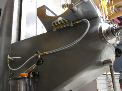
| Lube System and Junction | Photo by Kay Fisher |
I also measured and stared at the flexible hose for quite a long time before I decided that I did not need the 14” flexible hose and instead ordered a 12” hose.
I also got a good diagram for a 9 point lubrication system from
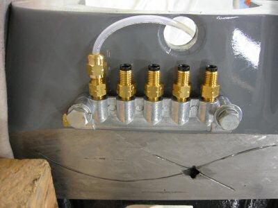
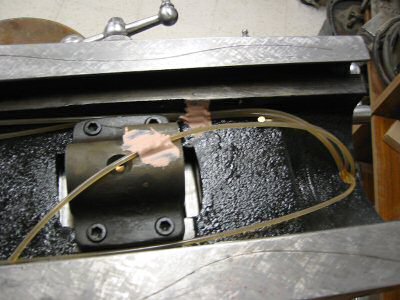
| 5 Port Junction on Saddle | Photo by Kay Fisher |
The junction should be located as close to the knee ways as possible because the tubing must make a sharp bend through the new drilled and reamed ¾ inch hole into the top of the saddle. I wish I had positioned mine about ¼” closer to the saddle.
| Saddle With Holes Drilled | Photo by Kay Fisher |
Instead of running the lines to the old zerk holes, I cross-drilled into the existing oil paths and installed (hammered in) drive barbs (elbow connectors) as per Michael Morgan’s suggestion. To make sure I didn’t miss the existing oil passageways, I inserted brass rods through the old zerk holes and made sure that my measurements agreed with my line of site observations.
| View of Saddle for Drilling | Photo by Kay Fisher |
I asked on the phone what size hole to drill for the drive barbs. The Lube USA fellow said 1/8”. This is correct for the barb but I drilled a couple sizes smaller and worked my way out to 1/8”.
| View of Saddle Plumbing | Photo by Kay Fisher |
To drill in the sides of the saddle I had to use a 90 degree drill adapter and screw machine (stubby) drill bits. I just barely had room. If you don’t have a screw machine drill bit you can easily just grind off the end of a cheap bit and make one.
One of my critical holes ended up just a bit little too large. I could have ordered the next size larger barb but instead I put a layer of solder on the old one and then it fit tightly.
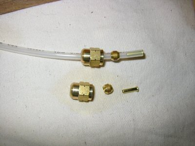
| 5/32" Tubing and Fittings | Photo by Kay Fisher |
The photo above shows the 5/32” tubing with a compression nut, 4mm tubing insert and 4mm compression sleeve.
I ended up using three #0 meters and the rest #1. A #1 meter puts out twice as much oil as a #0. I put the small #0 meters on the vertical ways and on the cross feed acme screw. Now the cross feed screw gets about 7 drops of oil per cycle. The vertical ways create the biggest mess so I am glad I took Michael Morgan’s advice and put #0 meters on them. I think since they are not under pressure from the weight of the table and because the knee moves less frequently they require less oil.
To get oil into the feed screws there is a hole on top of the feed nut bracket. Normally you center the table (with a mark on the saddle), remove a set-screw in the middle of the table and drip some oil through the hole.
| Feed Nut Bracket With Bondo | Photo by Kay Fisher |
I used bondo to fasten the 5/32 inch nylon tubing to the top of the feed nut bracket. Bondo was my second method of fastening. My first was not successful.
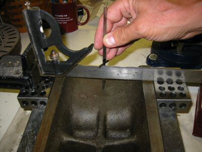
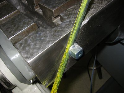
| Measuring for Feed Nut Oil | Photo by Kay Fisher |
After I fastened the tubing to the bracket I got to thinking it might not clear the bottom of the table. In the photo above I set up some 1 2 3 blocks and measured the depth across the entire bottom of the table. It was just a hair more than 5/32”. In hind site I should have ground a groove in the feed nut bracket with a Dremel tool and laid the tubing in it to have more free space.
In my case I elected to modify the original parts list from Lube USA “9 point lubrication system” for three reasons.
Instead of the 6 port junction mounted under the saddle I had a 5 port junction. Note even though it is called a 5 port junction there are actually 6 outlets. Five to the side and one out the end – where I installed a plug.
| Bondo Two Lube Lines | Photo by Kay Fisher |
I also used Bondo to fasten two lube lines that wanted to ride up as shown in the above photo.
I would do a few things differently if I had to do it again. I would change the layout on the left side of the knee to more closely match the layout pictured in the old Bridgeport manual that comes in Error Groff’s CD “Shaper Work Plus”. The meter on the left side of the saddle sticks out further than the elbow and meter on the right side of the saddle. If I laid out the lines as per the Bridgeport picture I could make the left like the right.
| Lubricator Layout | Photo from Bridgeport Manual |
| Lube on Right Side of Knee | Photo by Kay Fisher |
I would like to have used brass tubing even though it would have been a bit harder to work with.
There has been much discussion on the internet about the proper oil to use. Some have used 30-weight non-detergent motor oil. Some have used chain saw bar oil. I am using “Tru-Edge” brand special way oil 68. I purchased a gallon of it years ago long before I ever had a milling machine. However, the consensus is that the best choice is Mobil Vactra #2 way oil. If I ever run out of my current supply I plan to switch to Mobil Vactra #2. It is ISO grade 68 (SAE-20) and available for $13.82 a gallon as part number 60002151 from:
MSC Industrial Supply Co.
75 Maxess Road
Melville NY 11747-9415
(800) 654-7270
www.mscdirect.com
| System With Oil in Lines | Photo by Kay Fisher |
There is an advantage to the nylon tubing. It was very reassuring to see the way lube travel up the clear plastic tubes on all seven of the lines.
Last but not least – the job isn’t done until the zerk oil holes are plugged. I thought I might want to leave them in as an emergency way of supplying lube. Then I thought I might want to insert plugs made like set screws for easy removal. Finally I decided I just wanted the front to look as nice as possible with little evidence of the previous oil holes. I inserted four 1/8 NPT pipe plugs, ground the heads off with a Dremel wheel, and filed the stub down flush with the saddle.
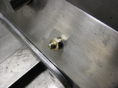
| Oil Zerk | Photo by Kay Fisher |
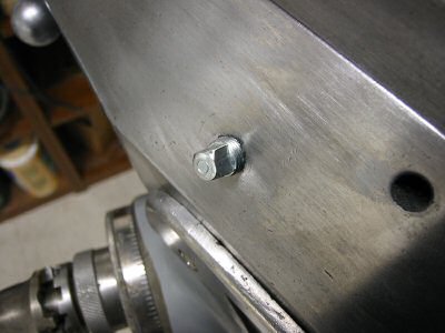
| 1/8" NPT Plug | Photo by Kay Fisher |
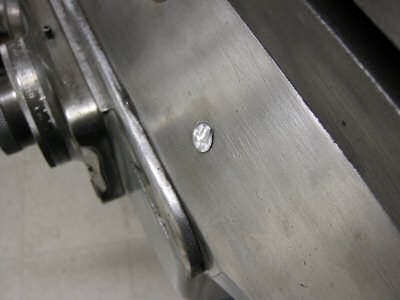
| Plug Ground Off by Dremel | Photo by Kay Fisher |
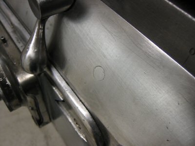
| Plug After Filing Down | Photo by Kay Fisher |
I am very happy with the one shot lube system. Now it is easy to oil and much more elegant!
The backlash in the feed screws was bad. I wasn’t too concerned about accuracy because I intended to install digital readout. However I just couldn’t bear to put it back together without making some attempt to reduce backlash.
| Feed Nut Bracket | Photo by Kay Fisher |
The feed nuts are both enclosed in the feed nut bracket. Like all fittings on this Bridgeport, they came out quite simply. This machine had apparently been in a greasy environment all of its 57 years. There is an important oil passage from the top of the feed nut bracket through both the longitudinal feed nut and the cross feed nut. You should remove both feed nuts and clean this out thoroughly.
There is a slit almost completely through the feed nuts as shown in the pictures below. This is the way the nuts come from the Bridgeport factory and they are installed while they are still in one piece.
| Feed Nut | Photo by Kay Fisher |
If you attempt to adjust them you will just get frustrated. They have to be removed first and cut through the rest of the way with a hack saw. Then reinstall them in the feed nut bracket and adjust out as much backlash as possible. When doing this make sure you test the full travel of the feed screw because your screw will be more worn at the center then at the ends. If you get it nice and tight in the center, it will bind when you traverse the table towards either end.
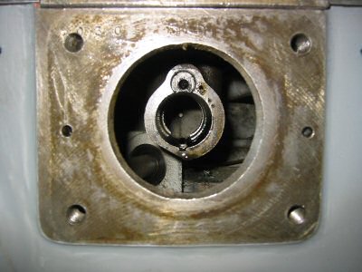
| Feed Nut Bracket in Knee | Photo by Kay Fisher |
I wish I had split my feed nuts when the table was out – but I didn’t. I had the entire table back together before I decided I really wanted to split the nuts. It is possible to remove them with the feed nut bracket in place. The above photo shows the view looking at the feed nut bracket through the front of the knee.
I hand-scraped the table’s dovetail ways in Massachusetts but didn’t install it on the saddle until months later in Arizona. Sure enough it was binding a little bit on the ends. I rigged up a measuring device and attempted to take the warp out of the ways. After 4 or 5 more scraping passes, it moved smoothly all the way across the longitudinal axis.

| Table Before | Photo by Kay Fisher |
I did more work on the table that is covered in the previously mentioned article on the one-shot lube system.

| Table With Spotting | Photo by Kay Fisher |
After mounting the table, I scraped the top, just to have it look nice.
| Table After | Photo by Kay Fisher |
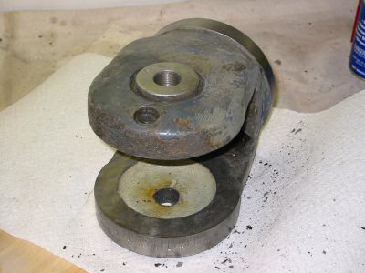
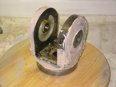
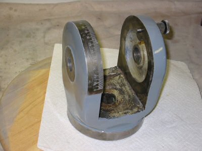
The knuckle (swivel adaptor) allows the head to be angled in both planes. This was a simple refinishing operation.
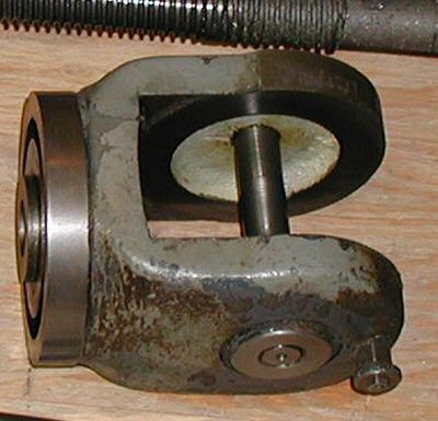
| Knuckle Before | Photo by Kay Fisher |
| Knuckle After Cleanup | Photo by Kay Fisher |
| Knuckle in Bondo | Photo by Kay Fisher |
| Knuckle Done | Photo by Kay Fisher |
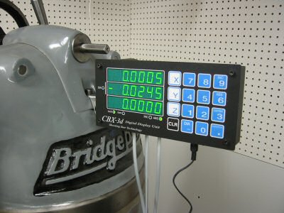
I installed a Shooting Star DRO on my previous Clausing milling machine. It worked well for me, so I ordered a new one for the Bridgeport. The real test of a vendor is how they handle problems. My first control unit had one defective button and the folks at Shooting Star sent me a whole new one very quickly.
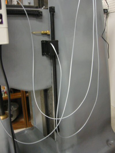
| DRO Z Axis | Photo by Kay Fisher |
One advantage of the Shooting Star system is that you can cut each scale to the exact length required. By comparison, DROs using glass scales can be cut, but cutting the scale voids the warranty.
For this machine, I bought a three-axis DRO. Some people put the third axis on the head. I chose to put it on the column. I plan to install a cheap digital indicator on the head later.
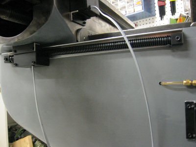
| DRO Y Axis | Photo by Kay Fisher |
The DRO installation was straightforward and much easier than the installation on my Clausing mill.
| DRO X Axis | Photo by Kay Fisher |
On the backside of the table there were two large coolant system drain holes. I plugged these before installing the X-axis. They were ½ inch NPT so I bought a couple of plugs at the local hardware store. They only went in a couple of turns so I tapped the holes deeper. To avoid the cost of a tap I turned a cheap plug into a tap by grinding a slot in it. I installed the plugs and sawed the ends off. Then I filed the stubs flush to the table.

| Plumbing Plug Tap | Photo by Kay Fisher |
| Cutting Head Off Plug | Photo by Kay Fisher |
| Cutting Head off Plug - Closeup | Photo by Kay Fisher |
| Filing Plug | Photo by Kay Fisher |
| Finished Plug | Photo by Kay Fisher |
| DRO Mounted | Photo by Kay Fisher |
X-Axis Power Table Feeds on milling machines are like DROs. To quote our NEMES founder Ron Ginger: "Once you have one you wonder how you ever got along without it before."
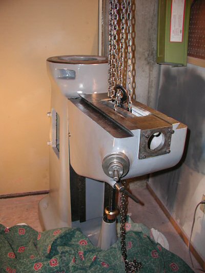
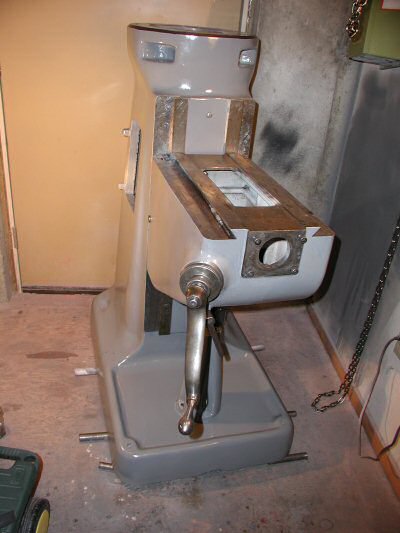
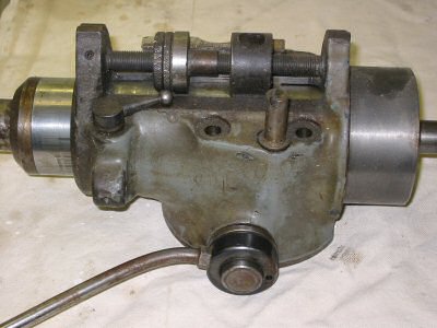
One of the reasons I wanted my old Round Ram M-Head Bridgeport was because it was the smallest Bridgeport milling machine ever made. Another aspect that made it desirable to me was the fact that it had the short (32 inch) table. Unfortunately it also had the original Bridgeport longitudinal power feed assembly which extended the length of the table another 4 inches from a stock 32 inch table. I figured the short Bridgeport with the small table would just fit in my basement where my old Clausing 8520 used to sit.
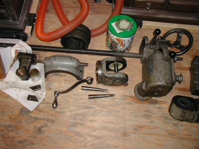
| Bridgeport Power Feed | Photo by Kay Fisher |
This massive and heavy assembly also came with no motor. I didn't care because I never intended to keep it anyway. Fortunately for me Dave Mahoney (my friend and fellow member of NEMES) wanted the parts inside the old power feed and was willing to trade me a much-needed belt housing and put new bearings in it. My old belt housing was usable but had some cosmetic problems.
I had a Harbor Freight power feed that I had installed on my Clausing for years and liked it a lot. It was difficult to install on the Clausing because the unit was designed to fit a Bridgeport. I knew I would have to work some magic because the power drive is designed to replace the manual crank and not the large heavy Bridgeport longitudinal power feed assembly. But I was able to succeed on the Clausing so I figured I could succeed on the Bridgeport. I sold the Clausing with the drive installed and ordered a new one from Harbor Freight for $179 - item number 34237-6ACA. This is their lowest powered unit; it has 135 ft. lbs. of torque.
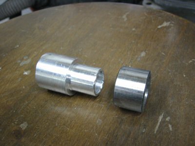
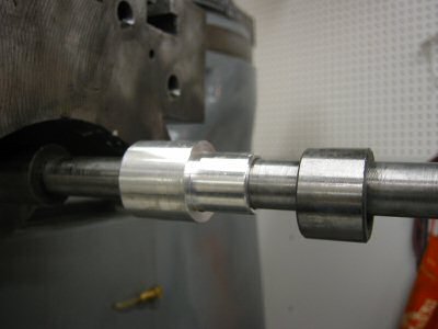
| Custom Bushing and Bearing Race | Photo by Kay Fisher |
The custom bushing (the left item in the above photo) was the only part I had to manufacture. The item on the right was the bearing race that came with the power drive. The bushing inside diameter is for a sliding fit over the longitudinal feed screw. The large outside diameter was some random scrap diameter. This is only needed to give a shoulder to the smaller end, which is a sliding fit with the supplied bearing race.
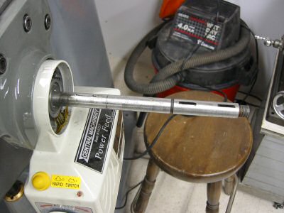
| Custom Bushing and Bearing Race on Shaft | Photo by Kay Fisher |

| Bushing and Bearing Race Slid Home | Photo by Kay Fisher |
The length of the bushing was such that the end result of the placement of the new bearing race was in line with the end of the roller bearing in the power drive as shown in the next two photos.
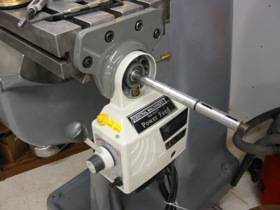
| Power Feed Mounted | Photo by Kay Fisher |
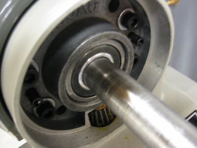
| Bearing Aligned with Race | Photo by Kay Fisher |
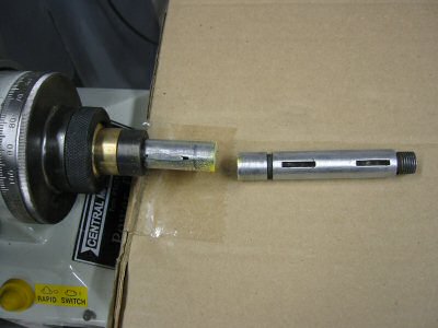
At this point in time I had a mounted power drive but needed to add two keyways like the original shaft except closer in.

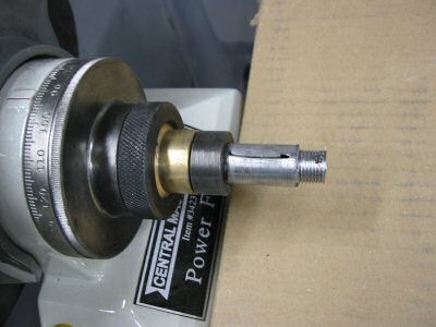
| Feed Screw with Dial Installed | Photo by Kay Fisher |
In the photo above I mounted the brass bevel gear, dial, and dial lock nut so that I could make a mark on the shaft with a felt tip pen to determine where I would cut the first keyway.
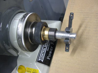
| First Keyway (On Left Above Yellow Label) | Photo by Kay Fisher |
I cut the keyways with a cutting wheel on a Dremel tool. It was crude but it worked. I would have liked to cut it with my mill but I sold my Clausing and had to get my Bridgeport running before I could do any milling.
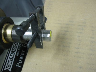
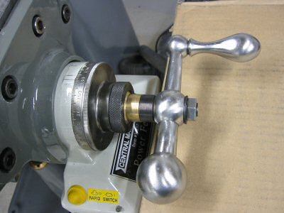
| Ball Crank Handle Mounted | Photo by Kay Fisher |
Next I mounted the ball crank handle so that I could again mark the location with a felt tip pen and cut the next keyway.
Next comes the moment of truth where I finally cut the end of the feed screw off with my hack saw. There is no turning back now.
| Shortened Feed Screw | Photo by Kay Fisher |
If I had a lathe large enough to handle the long feed screw, I would have used it to cut the threads. I didn't, so instead I cut threads the hard way.
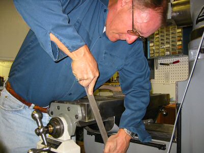
| Filing Feed Screw | Photo by Kay Fisher |
I filed the end of the longitudinal feed screw down by hand until the outside diameter was appropriate for cutting threads for the nut that holds on the ball crank handle. I used a machinist clamp for a file guide. I would take 10 strokes with a file then rotate the handle 40 thousands on the left dial then take another 10 strokes then rotate... All the while I kept checking the diameter with a micrometer As I approached the desired diameter I took less strokes and rotated the handle 20 thousands per filing cycle.
| Feed Screw Filed for Threads | Photo by Kay Fisher |
To thread the end I simply used a manual die and was very careful.
| Threading Completed | Photo by Kay Fisher |
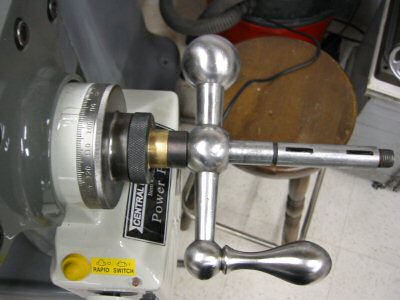
Below is a picture of the completed installation. When you put the nut on the shaft this is the first time you will actually compress the bevel gear against the gear in the power feed assembly. At this time you will have to add the supplied washer/shims as appropriate to get a nice freely moving mechanism. Not enough shims and the handle will take considerable force to turn and the gear will make bad sounds. Too many shims and the gear will feel really loose with too much backlash. This also adjusts the spacing that you see between power feed casting and the indicator dial. Note that the black spacer between the brass bevel gear and the handle is supplied with the power drive kit and is necessary for the handle to clear the power unit below it.
| Handle Installed | Photo by Kay Fisher |
| Limit Switches Installed | Photo by Kay Fisher |
The installation of the limit switches was simply one of bolting them in place. It was a lot harder on the Clausing.
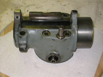
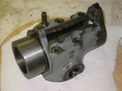
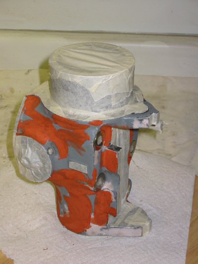
I didn’t take the M-Head completely apart because the previous owner had recently replaced the bearings.
| M-Head Before - Right Side | Photo by Kay Fisher |

| M-Head Before - Left Side | Photo by Kay Fisher |
I drove out the pin to remove the quill feed worm. Then I had to fasten a vice grip pliers to the shaft and hit it with a hammer. The secret to removing the quill feed pinion is to remove the set screw from the rear of the head. I sanded the fiber washers to abrade the surface.
| Bare M-Head Before - Right Side | Photo by Kay Fisher |
The clutch worked but I had to really tighten the clutch knob to engage it without some slipping. I cleaning this up and lubricated the shaft hoping this would make the clutch work easier. I used with moly grease (wheel bearing grease from the auto parts store that contains Molybdenum Disulfide (MoS2).
| Bare M-Head Before - Left Side | Photo by Kay Fisher |
One tricky thing about removing the head was removing the big aluminum belt housing. I took out the only bolt that holds it on but it wouldn’t budge. I hammered a big screwdriver into the slot and voila – it slid off easily.
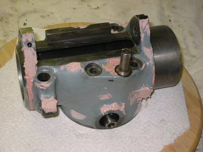
| M-Head with Bondo - Right Side | Photo by Kay Fisher |
I did take out the clock spring. It was tricky to get it back into the hole and hook it on the shaft. I suggest you wear gloves for this task.
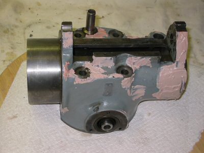
| M-Head with Bondo - Left Side | Photo by Kay Fisher |
Next is an explanation of the process of disassembling the M-Head. Part numbers mentioned below are from the manual available on CD mentioned earlier.

| M-Head in Spotting Putty - Right Side | Photo by Kay Fisher |
Remove the motor. Remove the belt guard housing (18). Remove the micrometer screw (66) by first removing the set screw (68) on the bottom right and the brass plug (67) behind it – then screw it out the bottom. The micrometer nut (60) and micrometer lock nut (62) will come out at this time. You have to spin them all the way off the top of the micrometer screw as you remove it.
| M-Head in Spotting Putty - Left Side | Photo by Kay Fisher |
Remove the micrometer stop (56) that is attached to the quill with a large Allen screw. Remove the quill lock bolt handle (65), then the quill lock bolt (64), then the quill lock sleeve, drilled (63).

| M-Head Painted - Right Side | Photo by Kay Fisher |
Now you can crank the quill up past the top stop and remove the brass quill skirt (29) – carefully! Mine is not brass? Now you can crank the quill all the way down and out of the head. Last, remove the quill lock sleeve, taped (69) from the bottom of the hole.
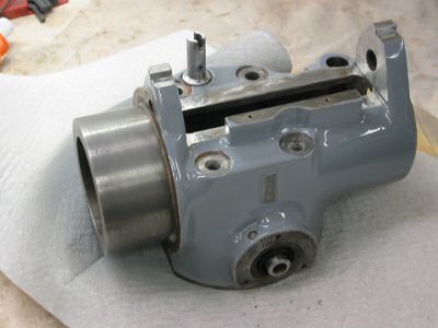
| M-Head Painted - Left Side | Photo by Kay Fisher |
Reverse the steps for reassembly but before you insert the quill, crank the clock spring 3.5 turns with the long rack feed handle.
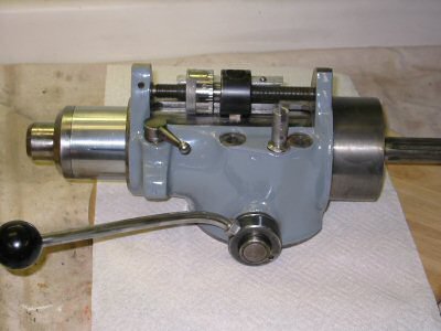
| M-Head Reassembled - Right Side | Photo by Kay Fisher |
I ordered a Quick Adjusting Quill Nut from ENCO for $24.95. Everybody sells them. In the High Quality Tools catalogue they are called the Educated Nut. It seems very well made and I am happy with my purchase. I used to crank the “slow” adjusting quill nut on my old Clausing back and forth till I was blue in the face. This should be a nice change.
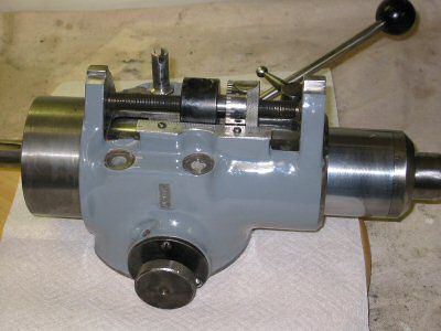
| M-Head Reassembled - Left Side | Photo by Kay Fisher |

| M-Head Quick Adjusting Nut | Photo by Kay Fisher |
| M-Head Installed | Photo by Kay Fisher |
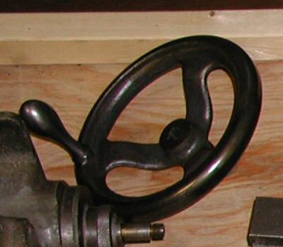
| Quill Worm Feed Hand Wheel - Before | Photo by Kay Fisher |
The old quill worm-feed hand wheel was painted black and had a dark red patina. I removed the paint and patina with a wire brush and polished it.
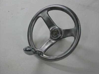
| Quill Worm Feed Hand Wheel - After | Photo by Kay Fisher |
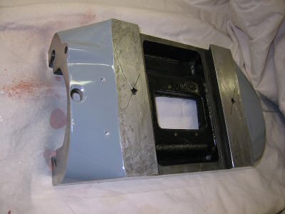
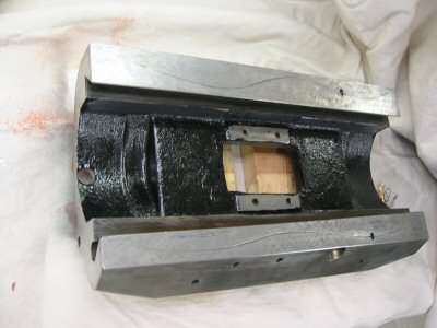
The belt housing was the most rewarding part to refinish. I started on it before anything else on the mill and finished it almost last.
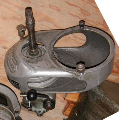
| Belt Housing Before | Photo by Kay Fisher |
My first problem was that one of the two motor housing ring studs had been broken out of the housing and a larger stud had been threaded in. It was a mess.
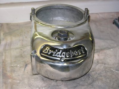
| Belt Housing Polished | Photo by Kay Fisher |
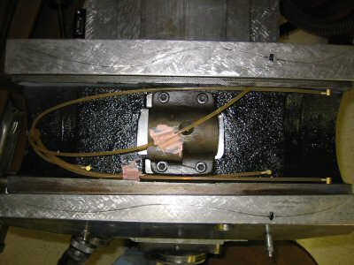
When I gave my Bridgeport mechanical longitudinal power feed to friend and fellow NEMES member Dave Mahoney, he returned the favor by giving me his undamaged Bridgeport belt housing. Dave also put two new bearings in the unit.
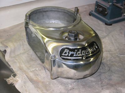
| Belt Housing Polished - Oblique View | Photo by Kay Fisher |
At this stage I wanted to retain the serial number plates so we swapped them back. Switching those darn plates was really tiresome. They were slightly different sizes, so I had to drill 8 new holes and tap them to mount the ID plates.
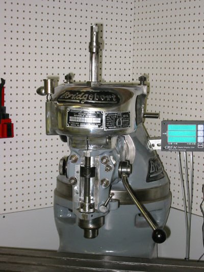
| Belt Guard Installed | Photo by Kay Fisher |
I had never done any large polishing before so that was quite a learning experience. I am quite happy with the way it looks.
The belt on my old M-Head was badly worn and about to fall apart. However is was in just good enough shape to make out a number on it that the local AutoZone store could look up in their chart. It is a 3L 3/8-inch belt 29 inches long. The replacement Kelly Springfield Utility Belt number is 84290.
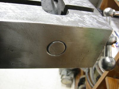
I enjoyed refinishing the parts that had raised brands and logos on them. The door looked pretty bad but with a few hours labor I was able to make it quite nice.
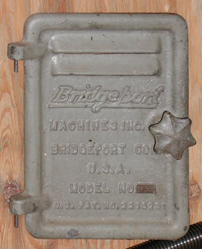
| Door Before | Photo by Kay Fisher |
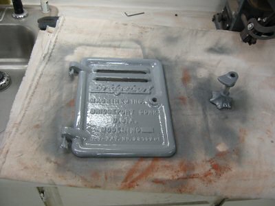
| Door After Gray Paint | Photo by Kay Fisher |
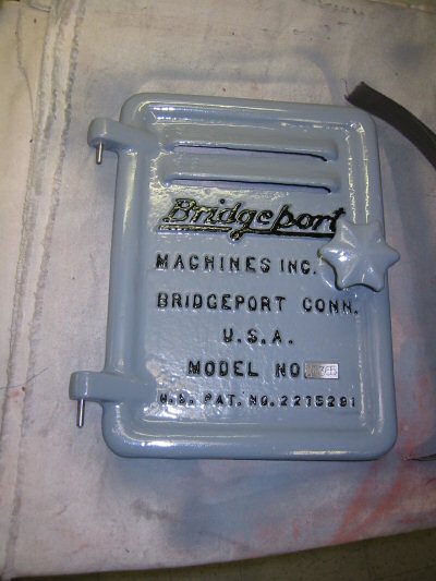
| Door After | Photo by Kay Fisher |
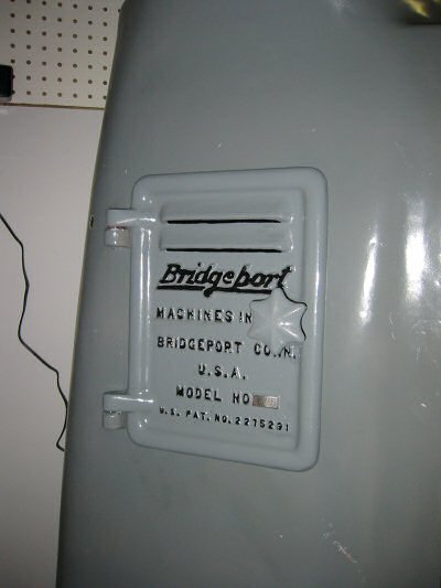
| Door Installed | Photo by Kay Fisher |
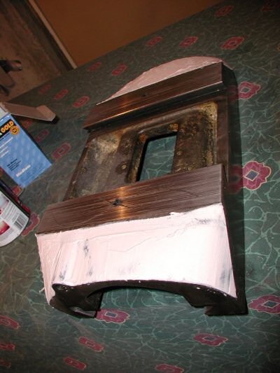
The shelf was a pleasant surprise. It was painted gray and had swarf embedded in it. I decided to remove everything with a nice big belt sander.
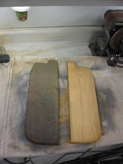
| Shelf Before & After Sanding | Photo by Kay Fisher |
Then a couple of coats of urethane and it started to look pretty good.
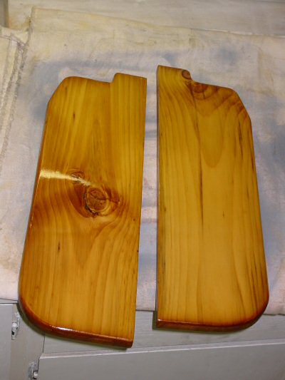
| Shelf Done | Photo by Kay Fisher |
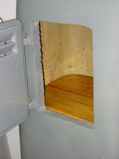
| Shelf Installed | Photo by Kay Fisher |
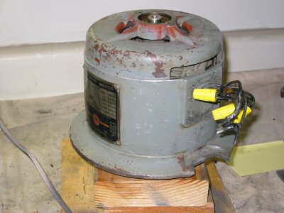
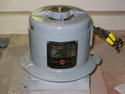
The motor worked, but the mounting slot on the right side of the motor flange was torn apart. Since I planned to power this with a VFD and not change belt position often it was not necessary to repair it, other than the fact that it didn’t look nice.
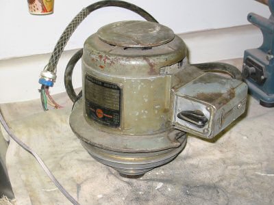
| Motor Before | Photo by Kay Fisher |
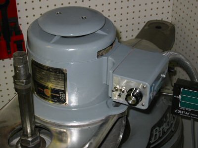
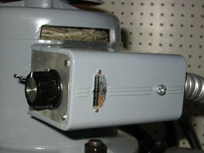
The Cutler Hammer forward reverse switch on the side of the motor would become a housing for the controls for a VFD. The guts of the switch were thrown away.
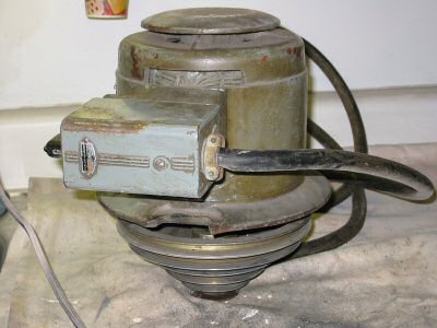
| Motor Mount Damage | Photo by Kay Fisher |
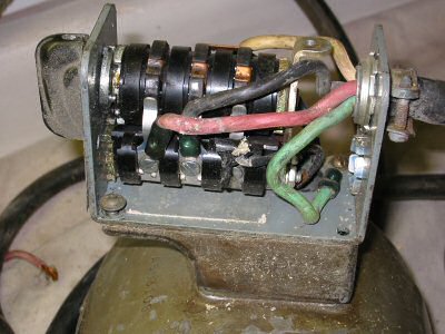
| Forward/Reverse Switch | Photo by Kay Fisher |
| Motor After Cleanup | Photo by Kay Fisher |
Most motors have a wiring chart on their label. This is what it said on mine:
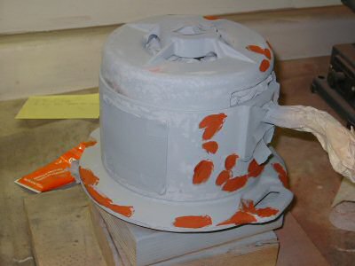
| Motor Primed & Spotted | Photo by Kay Fisher |
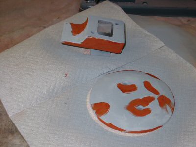
| Motor Parts Primed & Spotted | Photo by Kay Fisher |
| Motor Painted | Photo by Kay Fisher |
| Motor Parts Painted | Photo by Kay Fisher |
| Motor Installed | Photo by Kay Fisher |
With the motor installed, it was time to make it run without installing three-phase power to the shop. I asked around and snooped on the web for the cheapest variable-frequency drive (VFD) that I could find. This was disappointing research because the cheapest drives were from offshore eBay dealers. Prices were much higher from USA dealers. To complicate matters there were a lot of tales of radio frequency interference and many folks advised using a special filter so that your neighbors don’t loose their television or radio broadcasts.

| VFD Showing 24 Hertz | Photo by Kay Fisher |
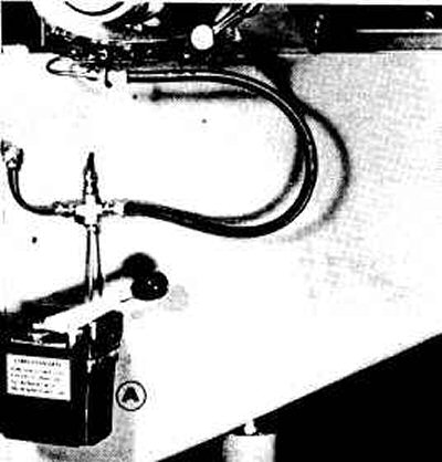
After much Internet searching and frustration I finally ordered a VFD from Clapool Controls in Livermore CA (925) 294 5915.
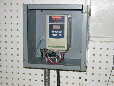
| VFD in Junction Box | Photo by Kay Fisher |
Ron Kemp, of Clapool Controls seemed very knowledgeable about VFDs and sympathetic to my cause.
The unit I picked out was a Genesis KBE2-2101-PF. This unit is made by
This small unit includes an RFI filter and costs $188 plus shipping. I also tried Electric Motor Service in Fremont CA (510) 651-2706. They returned my call 2 weeks later with a message from Lee that the same unit was $177.02. That’s a better price but it was too late.
| VFD Control Box | Photo by Kay Fisher |
Almost all VFDs allow for external controls. I mounted two toggle switches and a potentiometer inside the old Cutler Hammer forward/reverse switch housing. To insure that the vent holes of the VFD did not ingest some swarf I mounted the control unit in a standard electrical junction box. I replaced the junction box metal front panel with Plexiglas. Not only does this protect the VFD but it also makes it silent. Before I put it in the junction box you could hear the little cooling fan inside the VFD. It is comforting that the motor, belt, and bearings of the mill are so quiet that the VFD fan could be heard.
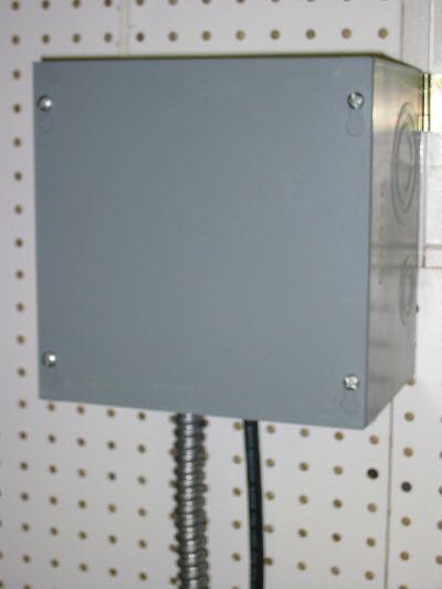
| Junction Box | Photo by Kay Fisher |
The junction box must be large enough that the VFD can circulate air and not overheat!
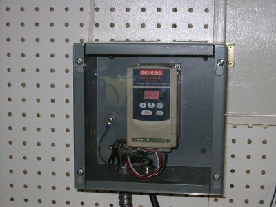
| Junction Box with Plexiglas | Photo by Kay Fisher |
I used rub on dry transfer labels for the front of the control unit. You can set the high and low frequency limits as well as things like the maximum current before overload protection on this VFD. This unit is rated for 1-horsepower but since I have a ½-horse motor, I adjusted the overload protection lower. You can also program the acceleration and deceleration time of the motor. I set mine to a minimum of 16 Hz and a maximum of 80Hz – which means I can run the old motor 33% faster than rated speed.
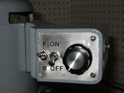
| VFD Controls | Photo by Kay Fisher |
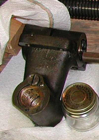
To remove collets, Ken Malsky, the mill’s previous owner, told me that you have to back off the drawbar nut then whack them out with a hammer. Sure enough, they sell special drawbar wrenches which in addition to a ¾” wrench also have a brass hammer. Yet, it seemed to me that the drawbar should eject the collet without a hammer.
When I tried to remove my first collet, I could not simply eject it with the drawbar as I had hoped. I had to whack it out with a hammer. I removed the drawbar assembly and took it apart. It was made to self eject. I tried several other collets with this draw bar. Some the drawbar could not even reach. Others it would just barely grab.
This drawbar measured slightly shorter than the published length in the “High Quality Tools” catalogue. High Quality Tools lists 3 different drawbars for M-head Bridgeports. Only two had 3/8 x 16 thread but one of those was one inch longer than the other. So my assumption is you get a different drawbar with your M-head depending on if it has #2 Morse taper, #7 Brown & Sharp taper, or B-3 taper. Perhaps this M-head drawbar was replaced with the wrong one. Perhaps at one time it was something other than a #2 Morse taper and the spindle was replaced.
I called Rice Machinery and got a quote on a replacement drawbar - $78.65. Wow – having a lathe and working mill I ought to be able to repair or remanufacture a drawbar. So I tried to figure out how I was going to stretch it.
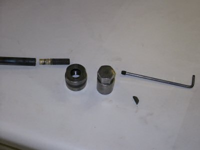
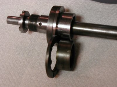
| Drawbar Parts | Photo by Kay Fisher |
The 3/8 x 16 threaded end of this drawbar is brazed into a bored out end of the drawbar. I heated it to glowing cherry read with a MAPP gas torch and was able to force the threaded stud out with a few washers and a nut.
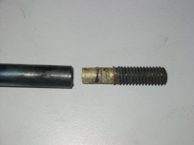
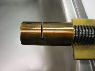
| Drawbar Threaded Stud | Photo by Kay Fisher |
I cut the head off a bolt that was one inch longer than the old threaded stud and turned the end to the same diameter. Then I heated the end of the drawbar and new stud to cherry red and hammered it back together. Now when you back off the drawbar knob it ejects the collet with little effort.
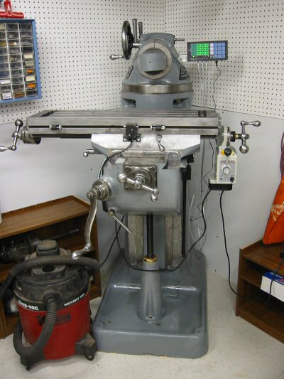
After two and a half years and one move across the country it is finally done.
| Completed - Left Side | Photo by Kay Fisher |
Done is relative of course. Someday soon I hope to add a digital indicator to the quill and perhaps a power drive for the Z-axis.

| Completed Top View | Photo by Kay Fisher |
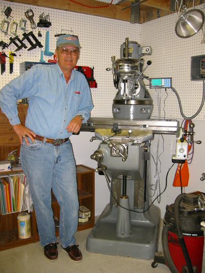
| Done At Last | Photo by Kay Fisher |
The photo above is me with my Bridgeport hat, my Bridgeport shirt, my Bridgeport belt buckle, and my newly finished 1947 Bridgeport. My Bridgeport coffee mug did not survive through the rebuild!
| Completed - Right Side | Photo by Kay Fisher |
| Completed - Front View | Photo by Kay Fisher |
My email address is KayPatFisher@gmail.com.